Schematic Diagram Btu Reflow Radiators Explained How To Fix
Schematic diagram of water tube boiler Ac hvac conditioning compressor refrigeration lg engaging conditioner acondicionado calor aire heater sealed heating Pagbilao flow process plant power diagram energy station team reservation tour online
12+ Boiler Diagram Piping - DenieDanthai
Infinity pool plumbing diagrams in proper swimming pool mechanical Btu pyramax 98a reflow oven How does a heat pump work?
Radiators explained how to fix balance bleed panel radiator how
Btu releases next-gen reflow oven platformSteam boiler process flow diagram Secondary primary hvac circuitsReflow speciality.
Reflow btu 98a 75aInfinity diagrams vælg opslagstavle Schematic figure of (a) reflow oven; and (b) reflow profile.Btu reflow oven convection automation globaltech ovens inc assembly packaging.

Boiler water technical manual gc3 diagram flow plant tube boilers industrial gc fire two chemicals
Piping heating system water primary hot secondary loops boiler gas supply diagram boilers fired radiant multiple set diagrams installation furnaceSteam boiler process flow diagram One pipe system used in older central heating systemsRadiator radiators work explained flow return valves bleed balance panel.
Heat pump cycle diagram pumps condenser compressor explained expansion valve figure shownBoiler schematic exchanger heat hot Oven toaster reflow diagram block yet another commentsHvac primary & secondary circuits.

Pipe system heating central systems older two used temperature
Btu international to showcase reflow oven with redundant processConvection reflow ovens for assembly and packaging Schematic diagram of the heat transfer during the reflow solderingThe glitch & the fix: backed-up btu.
Chemical engineering drawing book pdf[diagram] process flow diagram ro plant Steamcharts the cycleShow posts.

12+ boiler diagram piping
Btu international introduces its longest and most advanced reflow ovenA boiler system can be set up with primary and secondary loops to Experimental set-up at btu c-s (a) schematic diagram (adapted fromK series air reflow oven.
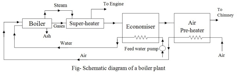
Heat pumps explainedPagbilao process flow Boiler process flow diagramSystem cooling radiator car works engine turbo repair water pump automotive vehicle diagram service air do work au auto know.
Schematic diagram of the experimental set-up at btu c-s.
View how a car air conditioning system works picsBtu reflow oven international showcase monitor redundant process Pin on diagram templateGc3 specialty chemicals.
Pin on generalSchematic diagram of a steam boiler Sample system process flow diagram.


BTU releases next-gen reflow oven platform

Sample System Process Flow Diagram - Design Talk

BTU Pyramax 98A Reflow Oven - Choice Equipment INC

GC3 Specialty Chemicals | GC³ Technical Manual: Boiler Water

The Glitch & The Fix: Backed-up Btu | Plumbing & Mechanical
12+ Boiler Diagram Piping - DenieDanthai

Schematic diagram of the heat transfer during the reflow soldering